Auto Live Load Generation
The program uses the following steps to generate live load on piers.
- Determine longitudinal reaction by moving truck in both directions
- Determine all possible transverse positions of trucks and solve for member responses
- Determine possible combinations of transverse positions and combined responses
- Select all sets that cause critical effects in any member
Moment Reaction on Integral Piers
This generation internally accounts for the pier view direction and then generates loads as per the view direction. When generating loads for multiple column pier or hammerhead pier, any of the four available options can be used. However, for integral piers, it is recommended that either option 3 (input longitudinal reaction) or option 4 (import reaction from CIP RC/PT Girder) be used. This is important because integral/monolithic piers resist some moment imparted from the superstructure, which is not generated when first two options are used. For the very first step program can either calculate the reaction internally or user can specify already computed lane and truck reactions or import the governing reactions from Precast/Prestressed Girder or CIP RC/PT Girder.
When the option to compute live loads longitudinal reaction for simple span is selected, program determines the maximum live load reactions for the selected trucks using simple span assumption (without the impact) along the longitudinal bridge direction. For double bearing lines, the program places each axle consecutively on each bearing line longitudinally and determines the different live load cases for reaction and torsion. Only those live load cases, which produce maximum reaction(s) and/or torsion(s) on the bearing lines, are selected for the next step of analysis. The uniform lane live load is multiplied by the length of live load and the shear rider (concentrated force) is added for calculating the reaction.
When you select the second option, Substructure computes the maximum continuous beam live load reactions at the pier for selected trucks. For double bearing line case, this load must be divided among the two lines. It is recommended to modify the reaction distribution among bearing lines. Substructure will then use the these factors to compute the load on each bearing line and then after transverse positioning, determine the critical load cases with critical bearing loads.
If you have already performed the live load analysis for superstructure which may be done using a continuous analysis, and you know the reaction at the pier, you can specify that using the third option. When this is specified, program computes the load on each bearing line using line factors. Further use of these reactions is somewhat different in AASHTO LRFD or AASHTO standard. When in AASHTO standard, if truck and lane reactions are specified, those are treated separately and are individually used for Step 2. However, in LRFD mode, live load contains load from truck axles as well as from Design Lane. Therefore, program uses both Truck and Lane and treats them as a single live load. When reversible cases are computed, program reverses the computed loads on bearings 1and 2 and may result in additional cases. When pier supports two unequal spans, you may generate load twice with separate factors rather than selecting the reverse option.
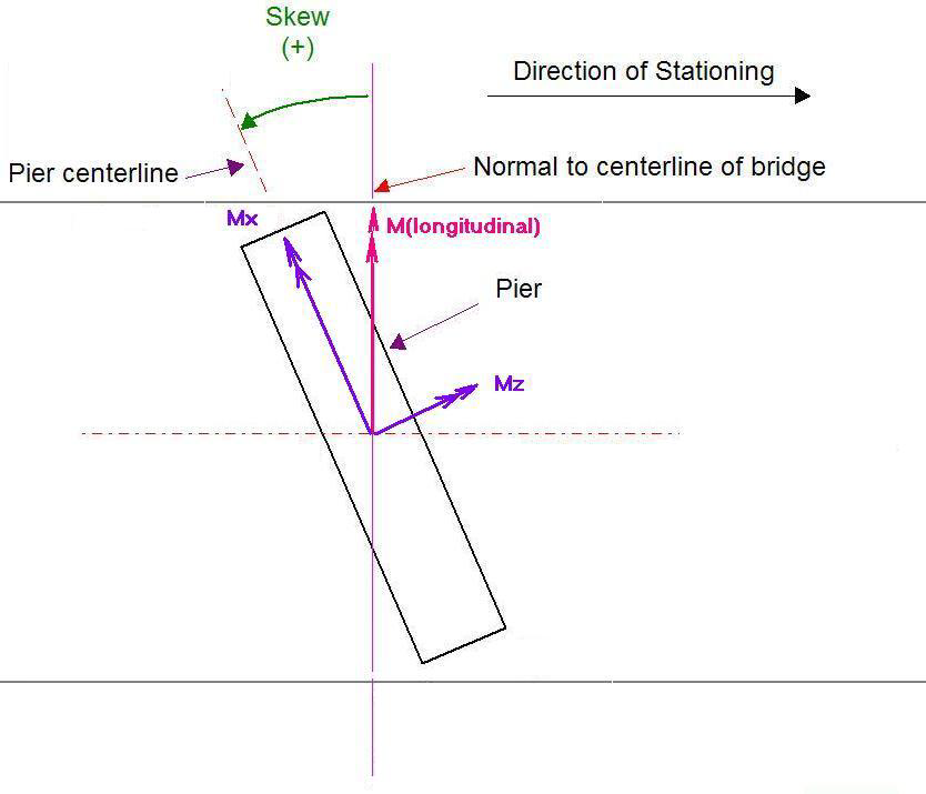
For integral piers, more input are needed than for hammerhead or multiple column piers (which are non-integral). For integral piers, vertical reactions as well as moment reactions need to be considered. As shown below on the direction for longitudinal moment input figure.
The fourth option lets you read the Precast/Prestressed Girder/CIP RC/PT Girder computed reactions. In order for you to use this option, you must first run analysis in Precast/Prestressed Girder/CIP RC/PT Girder and send the results using File: Send to Substructure. When results are read in Substructure, program provides information about supported spans for all piers but the program does not restrict the use of information if the information for the adjacent spans does not match. User must decide carefully about the reactions being imported. For integral piers, more inputs are needed than for hammerhead or multiple column piers (which are non-integral). For integral piers, vertical reactions as well as moment reactions need to be considered. Please see diagram below on the direction for longitudinal moment input. For integral pier, two sets of reactions are to be input. One set corresponds to maximum vertical reactions along with associated moment reactions for truck and lane. The other set corresponds to maximum moment reactions along with associated vertical reactions for truck and lane. In case of LFD design, program will read controlling load which could either be for lane or truck. In case of LRFD, program will read lane load as well as truck load. Truck load may be the controlling load of Design Truck, Design Tandem, Design Double Load or Design Double Tandem whichever trucks were included. Once these loads are read, the remaining procedure is very similar to the option of input of reaction.
For integral piers program uses the moment reaction along with vertical reaction as well. For each position, it uses the moment at the centerline of the position. The reaction for moment should be input in bridge axis system.
In the second step, the reaction(s) computed/manually input/read along the longitudinal direction in step 1 are distributed transversely across the bridge width. This is done by using either the Constant Spacing Method or the Variable Spacing Method. For non-integral piers program places the truck/lane load on deck and transfers the load to cap using lever rule and results in bearing loads. For integral piers the truck/lane load is applied directly to the cap. Therefore, for truck, program computes two concentrated loads on the cap and for lane load, it generates distributed load (UDL).
Multi-presence factor is considered in auto live load generation and the generated bearing loads are already reduced by the multi-presence factor for that load case. This is done on a load case basis because different load cases might have a different number of truck lanes present for which different values of the multi-presence factor should be used.
The following sections on constant spacing and variable spacing show how program determines transverse positions on the bridge. This approach is very similar for integral and non-integral piers. The figures however show only non-integral piers.